
Display Calibration – Part I
Display Calibration Poll Results
Last week, we polled MissingRemote readers regarding the calibration status of their displays and here are the results.
While the majority of you have calibrated your displays to some degree or another, roughly 25% have not and approximately 25% of you have either calibrated by viewing content or using settings found online. Almost 40% of you have calibrated with test patterns by eye and about 10% have gone all the way and either hired a pro or used a meter to calibrate. Whether you have calibrated your display or not, please read on where we will guide you step-by-step through the calibration process and explain exactly what it is all those controls in your display do to help you obtain optimal picture quality.
Introduction
Before making a purchase decision, a great many people will go out of their way comparing and contrasting displays. Part of that decision making process may be based on direct comparisons of pictures on the showroom floor. After all the painstaking comparisons have been made and the display is finally installed in its final location, it’s simply time to kick back, pop in a Blu-ray and enjoy the display in all of its glory, right?
Ironically, calibrating the display away from the factory defaults in most cases makes much more of a difference to enjoying a proper and accurate picture than any differences that exist between displays. On first thought, it may seem confusing why display manufacturers don’t ship displays that are picture perfect out of the box. However, if we consider the display manufacturer’s goal of selling as many displays as possible while competing on brightly-lit showroom floors with other manufacturers, it is clear that the displays that are configured for hyper-vivid images sell the most. To be fair, even if a manufacturer provides a perfectly calibrated mode out of the box (as some attempt to do with THX modes), it still will likely require calibration due to a number of circumstances.
Fortunately, calibrating the display to a more accurate and realistic picture is not too difficult. One of the things that make accurate images possible to obtain across a wide variety of source content is that content creators follow standards set by organizations such as the Society of Motion Picture and Television Experts (SMPTE) and the International Telecommunication Union (ITU). If we follow these standards across the entire content contribution, distribution and consumption chain, then we can see the content in its true and accurate form as intended by the creator and this is the goal of calibrating the display.
You may be tempted to hunt around online and find picture settings used by a professional review source or other owners; however, there are a lot of variables at play that make using these settings dubious when transferring to your own display. How can you be sure that the settings are even from a source device using the same color space or other possible differences? There may also be differences in displays due to normal manufacturing tolerances, different display firmware versions, etc. Furthermore, every viewing environment is different and can have different light characteristics that can impact the calibration results.
Another point that is often unmentioned is that display characteristics and source devices can and do change over time. For example, plasma phosphors age over time and LCD backlights and projector bulbs dim over time. Due to aging factors or changes in source devices (new Blu-ray player, new HTPC Graphics Processing Unit (GPU) or GPU driver, etc.), it is important to periodically calibrate or recheck a previous calibration. If the display has been used for less than 100 – 200 hours, the calibration should be rechecked once the display reaches the end of this “break-in” period as aging during this period is often more rapid, especially with plasma displays.
The rest of this article will focus on the basic calibration techniques that can be performed by anyone and form the basis for following articles that will take the next step in display calibration using a meter. Whether the calibration is performed with a meter or not, every calibration should begin using the techniques that follow. It is important to follow the steps in order, as each setting has the possibility of affecting the other settings. It is also important to calibrate for each source due to the differences that can exist between sources.
Speaking of different sources, a common configuration in home theater environments is one where an Audio Video Receiver (AVR) is used to switch multiple source devices onto a single HDMI cable. When this situation is encountered, there are a couple of possible options to allow for each source to have its own calibration. The first option is to use a different picture mode in the display that can be calibrated for each source. The second option is to employ an HDMI port multiplier after the AVR and use a separate HDMI input on the display for each source. Hopefully the display will allow for a different configuration on a per-port basis.
Step 1: Preparation
Before beginning display calibration, we first need some source material that includes test patterns that will allow us to accurately determine the proper display settings. For this article and subsequent articles, calibration patterns from AVS Forum named AVS HD 709 will be used. These patterns can be downloaded and used freely for personal use. There are also several other sources for calibration patterns that could be used such as Digital Video Essentials, Spears & Munsil, Avia, etc.
Another item that may be required for calibration if your display does not have a blue-only mode is a blue filter, available from several sources including THX. Usually, a display’s blue-only mode is more reliable as filters are known to be less accurate due to manufacturing tolerances and can degrade over time. Your display may call the blue-only mode “RGB Mode” or something similar.
Step 2: Color Space
If your source device is a Home Theater PC, it is important to understand that PC content such as games or desktop applications are generally produced in the RGB color space which uses Red, Green and Blue, each represented equally by level values 0 – 255. So black is R=0, G=0, B=0; white is R=255, G=255, B=255, 100% saturated red is R=255, G=0, B=0; etc.
Video content is encoded in the YCbCr color space where Y, Cb and Cr are represented equally by values 16 – 235, natively. Y represents luma (luma being brightness), Cb represents blue – luma and Cr represents red – luma. YCbCr is actually an encoding of RGB, which is used to represent all colors (unless you are Sharp J). The encoding from RGB to YCbCr is specified for HDTV signals by ITU-R Recommendation BT.709 or “Rec. 709” for short and this is the standard to which we will calibrate to. Devices such as Blu-ray players or other video source devices will generally always output YCbCr.
It should be noted that while the native YCbCr levels are 16 – 235, it is possible that levels below 16 and levels above 235 are possible. These non-native levels are referred to as blacker-than-black (BTB) and whiter-than-white (WTW), respectively.
Hopefully, the GPU used by the HTPC allows for a choice in color space. If your primary viewing material is video, it is probably best to output YCbCr. If you are more concerned with gaming or PC content, it is probably best to output Full-range RGB (levels 0 – 255). Some displays may only decode one of the color spaces and thus, there is no choice.
Sometimes there are other reasons to choose a certain color space. For example, a display might incorrectly decode the RGB color space. There are also certain AVRs that are known to clip RGB to levels 16 – 235 without any sort of conversion of the video levels. In that case, it would be best to output limited-range RGB (levels 16 – 235) so that the information could be properly converted by the source instead of being thrown away by the AVR.
The option to output YCbCr, full-range RGB or limited-range RGB is GPU and GPU driver dependent.
Step 3: Picture Mode and General Settings
It is generally best to find a picture mode on the display that is closest to a realistic picture to begin with. Usually a display will have a “movie” picture mode that will be the most realistic looking. To judge the realism, watch some content with faces as well as grass and trees. Look for the most natural looking skin tones. Skin hopefully isn’t unnaturally red and the grass and trees aren’t neon green looking.
You will then want to disable any dynamic picture settings. Things such as “Dynamic Contrast”, for example, should be disabled. Also, any picture tweaks such as “Black Tone,” “Skin Tone,” “Edge Enhancement,” noise filters, energy saving features, etc. should be disabled. Most of these settings will make the picture less accurate.
If you are dealing with an LCD display that has a backlight adjustment, turn this down to its lowest setting for the time being.
All color content is produced with a color temperature of 6500K or D65 to be exact. D65 is essentially the color temperature of daylight in Europe. If your display has a “Color Temperature” or “Color Tone” setting, it is generally best to set this to a “Warm” setting which will hopefully get the display reasonably close to D65.
Finally, it is important to allow the display to reach its normal operating temperature, so allow approximately 20 minutes of operation to occur before proceeding. In addition, you should be calibrating the display in your typical viewing environment.
Step 4: Setting Brightness (Black Level)
The brightness control determines the level of black (level 16 in video levels). The goal is to make level 16 be as black as possible while still being able to see all lighter video levels (17 and above). The Picture LineUp Generation Equipment (PLUGE) pattern (or “Black Clipping” pattern) located in chapter 1 of the Basic Settings on the AVS HD 709 disc will allow a perfect setting of your brightness control.
With the pattern, adjust the brightness control such that you can barely see level 17 and levels 18 and above are clearly visible as detailed in the image below. Level 16 and below should be completely black. Your black level is now correct.
 |
Make sure that black is not gray or “washed out.” If it does not appear as true black, your display may have a setting such as “Black Level” that applies to the level of black for RGB color space, if that is the output color space. If there is no adjustment, you will need to make sure that the source is outputting an appropriate signal that is compatible with the display device before continuing.
As previously mentioned, if you are adjusting RGB color space levels on an HTPC, there is usually a setting in the video card driver that will apply globally to all video content. Another approach would to be to adjust the software, if it has such a control.
*Note: Some manufacturers of plasma displays suggest that brightness control should not be set higher than 50% of the maximum setting during the first 100 – 200 hours of operation to help prevent the occurrence of image retention. Please consult your user manual.
Step 5: Setting Contrast (White Level)
The contrast control determines the level of white (level 235 in video levels). The goal is to make sure that white levels are not clipped to maintain as much white detail as possible and also establish a comfortable maximum light output. It is also important to understand that on some displays, many LCDs in particular, that if the contrast is adjusted too high, white may begin to take on the tint of another color.
While white is defined as level 235 in YCbCr, there is some small possibility that content may contain WTW values. There is some debate as to how much WTW content should be allowed to pass. If too little WTW content is allowed to pass, then the areas containing that information will be too white, however, the more WTW content that is allowed to pass, the less possible contrast there is in the image. Since there are competing goals (white detail vs. overall image contrast), a good middle ground is to allow levels up to 240 pass. At a minimum, levels up to 234 must not be clipped. The “White Clipping” pattern located in chapter 3 of the Basic Settings on the AVS HD 709 disc will allow a perfect setting of your contrast control.
With the pattern, adjust the contrast control such that levels 240 and lower are visible. At a bare minimum, levels 234 and lower must be visible as detailed in the image below.
 |
Once this primary objective is complete, the contrast setting should also be used to set a maximum light output that is comfortable for your eyes in the intended viewing environment. If the light output is too great, eye fatigue will set in. The correct setting will not clip white levels and result in the maximum comfortable light output.
If you are using an LCD display with backlight control, this is also an appropriate time to adjust the backlight. Set the contrast such that white levels are not clipped and then adjust the backlight to obtain a comfortable light output. Keep in mind that this adjustment can also affect your black level so it is a balancing act that must be played between maximum light output and black level.
It should be noted that Samsung plasmas have a “Cell Light” setting which, to some degree, is similar to the LCD backlight adjustment, but apparently without the negative effect of raising black level. It should probably be adjusted in a similar manner as the LCD backlight control.
Now that you have set the proper white level and light output, the black level should be checked again and adjusted slightly, if necessary. Repeat steps 3 and 4 as necessary until nothing is clipped and light output is correct.
*Note: Some manufacturers of plasma displays suggest that the contrast control should not be set higher than 50% of the maximum setting during the first 100 – 200 hours of operation to help prevent the occurrence of image retention. Please consult your user manual.
Step 6: Setting Color and Tint
The color (or saturation) control is an adjustment that increases or decreases simultaneously, the saturation of the red, green and blue color components. If saturation were completely removed, the image would be gray; if the saturation were maximized, then red would be too red, green would be too green and blue would be too blue.
The tint (or hue) control is an adjustment that essentially shifts the colors towards each other. For example, the control can simultaneously make red more blue, green more red and blue more green or the opposite.
Remember, the goal is to meet the Rec. 709 standard which precisely defines the characteristics of red, green and blue. The “Flashing Color Bars” pattern located in chapter 4 of the Basic Settings on the AVS HD 709 disc will allow a the color saturation and tint controls to be set as accurate as possible by eye.
With the pattern playing, engage the display’s blue-only mode or view the display through a blue filter and adjust the color and tint controls such that the flashing boxes are neither too dark or too light. Ideally, the blue color inside and outside the flashing boxes will be exactly the same.
 |
Step 7: Setting Sharpness and Overscan
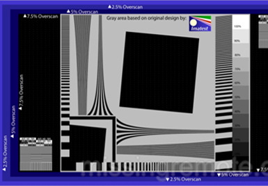
The sharpness control in many displays will be optimum at the minimum setting, however, some displays will benefit by adjusting the sharpness setting higher than the minimum. Keep in mind that some displays may feature undefeatable sharpening or edge enhancement and in such cases, the result of adjusting the sharpness control may not entirely correct for the errors introduced by these processing techniques. The “Sharpness and Overscan” pattern located in chapter 5 of the Basic Settings on the AVS HD 709 disc will allow the sharpness setting to be set properly and determine if there is any overscan present.
With the pattern, adjust the sharpness control to its minimum setting and then adjust it as high as possible without seeing the edges of objects turning bright white or curved lines becoming blocky or jagged. Ideally, there should be no moiré present. If your display has an edge enhancement control, you may wish to use this pattern to check any ill effects that it may bring.
 |
Ideally, you want to see every pixel in the source that is present. If you can’t see the full pattern as shown above, try to find a setting in the display such as “Just Scan”, “Screen Fit”, etc. so that pixels are mapped 1:1 and there is no overscan. It is also possible that the source is configured to stretch or zoom the image in such a way that overscan is created or the squares in the pattern become distorted.
Conclusion
This concludes the basic calibration of your display. As a final step, watch some content and see how it looks. If things don’t look right, start from the beginning and repeat the steps to double-check anything that might have changed or not been adjusted correctly.
If you happen to be the owner of a 3D-capable display, you will want to calibrate another picture mode for use when 3D content is played. Remember to have your 3D glasses on and the display’s 3D mode engaged during the calibration.
Some displays can take 24p input and properly maintain the original film cadence, however, when doing so, the display characteristics may change due to the different processing, thus, it would be ideal to calibrate a picture mode in that instance if your source device will be switching between 50Hz/59.94Hz video content and 23.976Hz film content.
As we said before, this is only Part I of our display calibration guide. In Part II, we are going to take calibration to the next level by detailing and explaining how to calibrate your display with a meter which can achieve a level of image accuracy that far exceeds what is capable by eye using test patterns.