
DIY 433MHz “Smart” Wi-Fi switches with Amazon Echo and Vera Control support
I’m not sure exactly why my wife came home with a cheap (£10-15) set of 433MHz remote controlled switches. While I gave her some grief initially, I’m glad she did. Because for a few £ more we now have four “smart” IP switches that can be controlled from a home automation controller (HAC). And since we have an Amazon Echo, voice as well.
Problem
It really bugged me that we had these remote control switches and they didn’t integrate with the rest of the system. A few approaches to programmatic integration were attempted. First, I tried to catch/decode/transmit the signals sent by the remote. While this should work in theory, I wasn’t able to get it going, I suspect this had to a lot to do with the quality of the components I was using, but there could easily have been other factors as well. After thinking on it a while, it occurred to me that it would be significantly easier to reuse the existing remote. Grab your soldering iron, and let’s get to work.
Setup
What we need:
- 1x 433MHz remote switches (I’m not actually sure where she bought these, some local shop)
- 1x ESP8266 WeMos D1 Mini (£1-9)
- 8x BC547B transistors (£0.99)
- 8x 10K resistors (~£1 for 100)
- 1x 400 point breadboard (£2)
- Breadboard wires
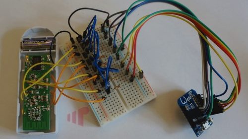
Most of the work is simply mapping the buttons on the remote. I did this using a single wire to simulate a press by connecting the circuit (black wire to various points on the board). When each button is located, solder a wire to that point.
- Insert the transistors in a column from the bottom to the top (I used “h”).
- Connect the group wire (in this case green) from the WeMos to the breadboard, then use as many wires as necessary to bridge ground to the remote and each bottom pin of the transistors (blue wires)
- Connect each pin D0-D3, D5-D8 (D4 can be used, but since it’s tied to the LED it will stay lit all the time) to the row corresponding to the middle pin of the transistor.
- Insert a 10K resistor across the breadboard bridge in line with the wire inserted in 3 and the middle pin of the transistor.
- Connect a remote button wire to the top pin of each transistor. Using this layout:
D1 — Switch 1 On
D2 — Switch 1 Off
D3 — Switch 2 On
D0 — Switch 2 Off
D5 — Switch 3 On
D6 — Switch 3 Off
D7 — Switch 4 On
D8 — Switch 4 Off
Software
Grab a copy of ESPlorer for editing and exporting the files to the WeMos, then download the webserver files from GitHub. Assuming you followed the wiring scheme above only wifi.txt will need to be edited.

Change the first two lines to have the name of your SSID and the password required to connect. If you’re running 192.168.1.x, leave the rest alone. Just make sure to add a static DHCP assignment (or change the third line to a safe static IP) in the router. Upload the files and it should startup the webserver exposing each button.

While the UI is nice and a great endpoint if you don’t have a HAC, it was not the end goal for me. For that, we need to integrate the button presses into these centralized systems. Initially, I did this with a Vera Control system using scenes. Each button press corresponds to a URL in the format “http://192.168.1.99/X” where X is the digital input on the WeMos (e.g. D1 = 1). Calling this is simple with a bit of LUA in the Vera:
luup.inet.wget(“http://192.168.1.99/1”, 5)

This worked great. But when we got an Amazon Echo, I ended up using a different mechanism to manage each “device” leveraging BWS Systems “HA Bridge”. It’s great for many reasons, including Harmony and Vera integration. But, it also allows you to make discrete HTTP GET requests in a custom device.

So while it is possible to set it up to use the Vera’s scenes (one for On, one for Off), it’s more efficient to just call the necessary URLs directly to turn a switch on and off.
Credits
- The UI for this project was based on an earlier version of this https://github.com/mrkale/NodeMCU-WifiDoubleSwitch. Its use of POST instead of GET made it unsuitable for what I wanted to accomplish, but I liked the simplicity of the interface so it was borrowed.
- The webserver was based on https://www.youtube.com/watch?v=5ElOFNiphGA. The ESP8266 has very little memory, so it wasn’t possible to write out the web UI without significant nesting otherwise. This also allowed for much cleaner design; separating functionality from UI.